2-2R DAC with Arduino
Karol, 21 July 2020
R - 2R is one of the simpliest way to perform digital to analog conversion. In combination with Arduino,
which lacks a build-in DAC, it seems to be a good thing. Let's make a simple example with this type of DAC creating sinewave generator and using Citron Maker UNO.
Firstly, I made a circuit on breadboard, checked if everything is working and so on, but now I will show and discuss the schematic
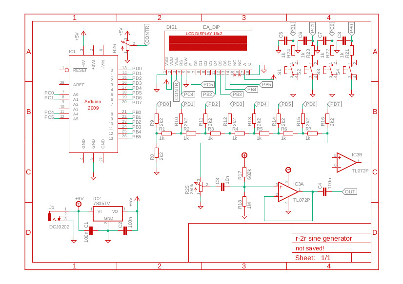
The resistors R1-R16 form the discussed digital to analog converter. Here is nicely explained how R-2R DAC works.
I buid 8-bit DAC, so maximum voltage value (5V) is represented as 255. The resolution achieved by 8-bit DAC is 5V/28 and this equals 0.0195 Volts. It's quite good. The resultion can be easily increased by adding more resistors in ladder, but we are limited by arduino output pins. The output resistance of DAC equals 1kΩ. R25 controls the output amplitude. The op-amp is used in voltage follower combination, so I achieved big output resistance. R17 and R18 were used to shift the signal before op-amp so it wasn't clipped at the output. The C4 removes constant component from the signal.
R21-R24 and C5-C8 are for debouncing purposes. The Citron Maker UNO doesn't have DC barrel jack for powering the board, also it lacks of 5V regulator. I had to make my own, litlle powering circuit including lm7805 and two capacitors, The circuit was powered with 9v battery. R26 is responsible for setting the contrast of 2x16 LCD on which can be displayed the data.
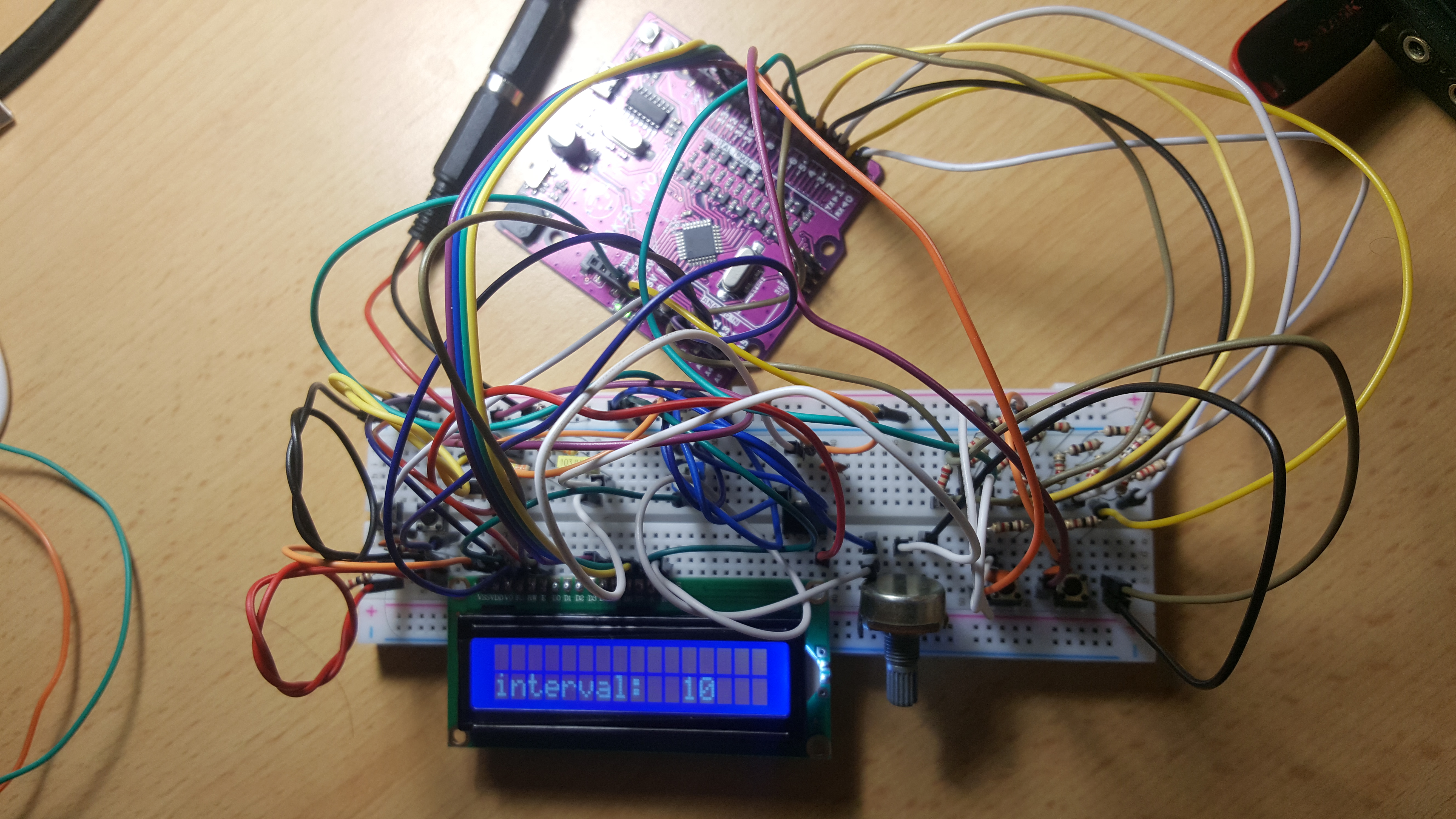
I putted some code on the Arduino and started experimenting. Via buttons there is possibility to change the frequency of the signal (Changing the interval using interrupts). I used a lookup table generated with this Website. There is also implemented simple displaying the interval on the LCD. I hope the code is clear.
  #include "PinChangeInterrupt.h"
  #include <LiquidCrystal.h>
  #include <math.h>

  #define FREQ_up A0
  #define FREQ_down A1
  #define FREQ_up5 8
  #define FREQ_down5 9

  LiquidCrystal lcd(A4,A5,10,11,12,13);


  unsigned char sinewave[64] =
  {
  128,140,152,165,176,188,198,208,
  218,226,234,240,245,250,253,254,
  255,254,253,250,245,240,234,226,
  218,208,198,188,176,165,152,140,
  128,115,103,90,79,67,57,47,
  37,29,21,15,10,5,2,1,
  0,1,2,5,10,15,21,29,
  37,47,57,67,79,90,103,115,
  };


  byte pointer = 0;
  volatile unsigned int interval = 10;
  char line1[16];
  char line0[16];


  void setup() {
    // put your setup code here, to run once:
    lcd.begin(16, 2);
    lcd.clear();
    lcd.setCursor(0,1);
    sprintf(line1,"interval: %3d",interval);
    lcd.print(line1);
    pinMode(FREQ_up, INPUT_PULLUP);
    pinMode(FREQ_down, INPUT_PULLUP);
    pinMode(FREQ_up5, INPUT_PULLUP);
    pinMode(FREQ_down5, INPUT_PULLUP);
    attachPinChangeInterrupt(digitalPinToPinChangeInterrupt(FREQ_up), freqUp, FALLING);
    attachPinChangeInterrupt(digitalPinToPinChangeInterrupt(FREQ_down), freqDown, FALLING);
    attachPinChangeInterrupt(digitalPinToPinChangeInterrupt(FREQ_up5), freqUp5, FALLING);
    attachPinChangeInterrupt(digitalPinToPinChangeInterrupt(FREQ_down5), freqDown5, FALLING);
    DDRD = B11111111;
  }

  void freqUp() {
    if (interval > 1){
    interval -= 1;
    }
    lcd.setCursor(0,1);
    sprintf(line1,"interval: %3d",interval);
    lcd.print(line1);
  }

  void freqUp5() {
    if (interval > 5){
    interval -= 5;
    }
    lcd.setCursor(0,1);
    sprintf(line1,"interval: %3d",interval);
    lcd.print(line1);
  }

  void freqDown() {
    if (interval < 400){
    interval += 1;
    }
    lcd.setCursor(0,1);
    sprintf(line1,"interval: %3d",interval);
    lcd.print(line1);
  }

  void freqDown5() {
    if (interval < 395){
    interval += 5;
    }
    lcd.setCursor(0,1);
    sprintf(line1,"interval: %3d",interval);
    lcd.print(line1);
  }

  void loop() {
    // put your main code here, to run repeatedly:

    PORTD = sinewave[pointer] & 0xFF;
    pointer = (pointer + 1) & 63;

    delayMicroseconds(interval);

  }
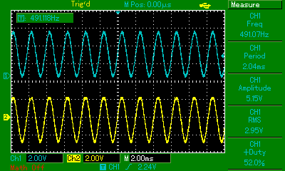
So I achieved pretty nice sinewave. Max frequency I've achieved is about 9kHz. The blue sinewave on osciloscope is measured on 3rd pin of R25. Yellow one is at the output (after C4)
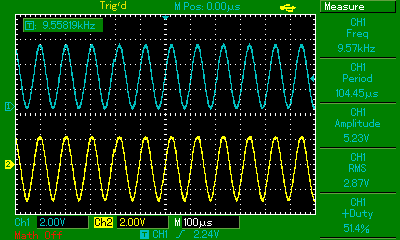
The R25 pot gives possibility to change the amplitude of the signal.
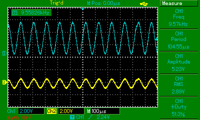
And via buttons we can change the frequency.
And there it is, sinewave generator using Arduino, and some basics electronic elements. There are some better ways to generate sinewave of course, but I think that was good example how to use and change arduino outputs at the same time, use interrupts etc. I won't use it as sinewave generator, because it has too small frequency range. In some time im going to build function generator based on ICL8038 which will have better performances.
